[ROMAPI]XPI系列:访问FLASH OTP – 功能分析与实战
XPI系列:访问FLASH OTP - 功能分析与实战
1. 前言
注意:本文涉及的写OTP以及禁用OTP更新操作为不可逆操作,请仅在应用有此需求的前提下谨慎操作。
在众多系统应用场景中,常常需要将特定数据存储于 FLASH OTP(One-Time Programmable)区域,例如系统参数、产品序列号等关键信息。借助先楫提供的XPI底层API接口,用户能够便捷地达成对OTP的操作。
本文以MX25L12833F为例,基于面向xSPI接口的API,详细阐述如何使用XPI底层API实现FLASH OTP的读写等操作。
2. 功能分析
2.1 实现思路
首先,通过查阅该FLASH芯片的数据手册(datasheet),我们可以明确以下操作要求:
进入OTP模式
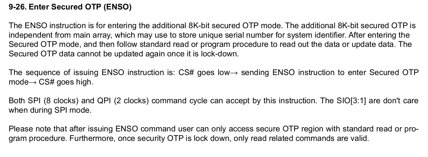
若要访问片上 OTP 区域,必须先发送Enter Secured OTP(ENSO:0xB1)命令,之后方可进行 OTP 的读写操作。退出OTP模式
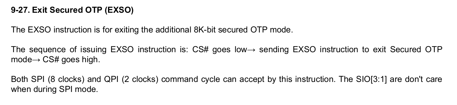
当结束对片上 OTP 区域的访问时,需先发送Exit Secured OTP(EXSO:0xC1)命令,之后才能正常对 FLASH 的主存储区域进行读写操作。OTP读写命令
片上 OTP 的读写命令与主存储区域的读写命令完全相同。在此,回顾一下主存储区域读写的相关要求:- 进行写操作之前,需要发送
Write Enable(WREN:0x06)命令。 - 发送完写操作命令后,要通过
Read Status Register(RDSR:0x05)命令,检查 FLASH 是否处于WIP(Work In Progress)模式。 - 只有当 FLASH 未处于
WIP模式时,才能正常读取 OTP 区域。
- 进行写操作之前,需要发送
永久禁用OTP写操作
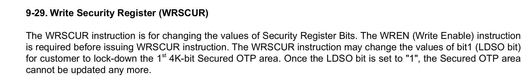
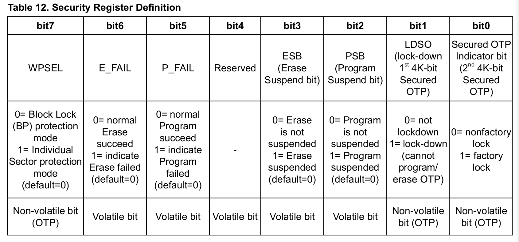
若要永久禁用对片上 OTP 区域的写操作,需先发送Write Security Register(WRSCUR:0x2F)命令。由于需要改变 security register 中的某一位,所以还需实现Read Security Register(RDSCUR:0x2B)命令。
通过以上步骤,可以确保对OTP区域的操作符合芯片规范,同时避免误操作导致的功能异常。
基于上述描述,我们需要实现以下函数:
- 进入 OTP 模式
- 退出 OTP 模式
- 写使能(WREN:0x06)
- 写 OTP
- 读状态寄存器(RDSR:0x05)
- 读 OTP
- 读 Security Register
- 写 Security Register
- 永久禁用 OTP 写操作
在实现之前,我们还要结合SoC的架构特性、XPI特性以及FLASH OTP访问的的一些限制,我们总结出以下注意事项:
2.2 注意事项
根据MX25L12833F的数据手册,进入 OTP 模式后,CPU 将无法正常读取主存储区域。因此,在执行 OTP 操作时,应尽可能避免对 FLASH 主存储区域进行读取操作。若不可避免地发生了读操作,也需要能够消除该操作带来的影响。
在先楫的 MCU 上,以下操作可能会触发非预期的读 FLASH 主存储区域操作:
| 可能触发读操作的场景 | 是否可规避 | 规避/消除影响的方式 |
|---|---|---|
| 系统中断 | 是 | 禁用全局中断,或者将中断服务函数以及服务函数中调用的所有函数都放在 RAM 中执行 |
| 当前代码的执行 | 是 | 将在访问 OTP 期间需要执行的代码放置到RAM中执行 |
来自其他master的访问 |
是 | 在系统的业务逻辑中避免此类操作 |
| CPU的预取操作 | 是 | 禁用预取操作,或者在恢复访问主存储区域前,消除预取操作带来的负面影响 |
综合上述场景,我们可以采用以下方法来规避大多数的读 FLASH 主存储区域操作:
- 访问OTP期间禁用全局中断。
- 将访问OTP相关的代码放置到
RAM中执行。 - 在恢复访问主存储区域前,清除
XPI预取Buffer并清除I-Cache。
需要注意的是,实际操作中是否按照上述步骤执行,需要根据具体的应用场景进行选择。此外,其他master的访问(如通过 DMA/USB等访问)相对较难禁止,需要在业务逻辑层面进行规避。
3. 具体实现
以下为具体代码实现:
3.1 进入OTP模式
ATTR_RAMFUNC hpm_stat_t mx25l12833f_enter_secured_otp_mode(XPI_Type *base,
                                                           xpi_xfer_channel_t chn)
{
   /* 创建命令序列 */
    xpi_instr_seq_ctx_t ctx;
    xpi_instr_seq_init(&ctx);
    xpi_instr_seq_add_cmd_phase(&ctx, 0xb1, 1, false);

    hpm_stat_t status = xpi_send_cmd(base, chn, &ctx, 0);
    return status;
}
3.2 退出OTP模式
ATTR_RAMFUNC hpm_stat_t mx25l12833f_exit_secured_otp_mode(XPI_Type *base,
                                                          xpi_xfer_channel_t chn)
{
    /* 创建命令序列 */
    xpi_instr_seq_ctx_t ctx;
    xpi_instr_seq_init(&ctx);
    xpi_instr_seq_add_cmd_phase(&ctx, 0xc1, 1, false);

    hpm_stat_t status = xpi_send_cmd(base, chn, &ctx, 0);
    return status;
}
3.3 写使能
ATTR_RAMFUNC hpm_stat_t mx25l12833f_write_enable(XPI_Type *base,
                                                 xpi_xfer_channel_t chn)
{
    /* 创建命令序列 */
    xpi_instr_seq_ctx_t ctx;
    xpi_instr_seq_init(&ctx);
    xpi_instr_seq_add_cmd_phase(&ctx, 0x06, 1, false);

    hpm_stat_t status = xpi_send_cmd(base, chn, &ctx, 0);
    return status;
}
3.4 读状态寄存器
ATTR_RAMFUNC hpm_stat_t mx25l12833f_read_status_register(XPI_Type *base,
                                                         xpi_xfer_channel_t chn,
                                                         uint8_t *status_reg)
{
    /* 创建命令序列 */
    xpi_instr_seq_ctx_t ctx;
    xpi_instr_seq_init(&ctx);
    xpi_instr_seq_add_cmd_phase(&ctx, 0x5, 1, false);
    xpi_instr_seq_add_read_phase(&ctx, 1, false);

    /* 读寄存器 */
    hpm_stat_t status = xpi_read_data(base, chn, &ctx, 0, status_reg, 1);
    return status;
}
3.5 写OTP
在实现该函数时,需要注意以下要点:
- 根据文档说明,写 OTP 的指令与读主存储区域的命令一致,这里我们选择Page Program(PP:0x02)命令来实现写 OTP 操作。
- 进入 OTP 模式后,CPU 无法正常读取主存储区域,因此在进入 OTP 模式前需要采取以下保护措施:
- 关闭全局中断,防止函数执行过程中意外访问 FLASH 主存储区域。
- 该函数不允许放在 FLASH 中执行,本示例中将代码放在 RAM 中执行。
- 在退出 OTP 模式后,恢复主存储区域读取前,需要执行以下操作:
- 清除 XPI AHB buffer 中预取的数据。
- 执行
fencei清除I-Cache,以防在写 OTP 的过程中,由于 CPU 的分支预取导致I-Cache中被加载了无效的指令。 - 恢复全局中断状态。
ATTR_RAMFUNC hpm_stat_t mx25l12833f_program_secured_otp(XPI_Type *base,
                                                        xpi_xfer_channel_t chn,
                                                        uint32_t offset,
                                                        const uint8_t *otp_data,
                                                        uint32_t size_in_bytes)
{
    hpm_stat_t status;

    /* 创建命令序列  */
    xpi_instr_seq_ctx_t ctx;
    xpi_instr_seq_init(&ctx);
    xpi_instr_seq_add_cmd_phase(&ctx, 0x2, 1, false);
    xpi_instr_seq_add_addr_phase(&ctx, 24, 1, false);
    xpi_instr_seq_add_write_phase(&ctx, 1, false);

    /* 关全局中断 */
    uint32_t level = disable_global_irq(CSR_MSTATUS_MIE_MASK);

    /* 进入 OTP 模式 */
    mx25l12833f_enter_secured_otp_mode(base, chn);

    /* 写 OTP
     * 注意:此处需要保证写操作不跨页边界,否则会出错。
     */
    uint32_t remaining_bytes = size_in_bytes;
    uint32_t program_addr = offset;
    uint8_t *program_buf = (uint8_t *)otp_data;
    while (remaining_bytes > 0) {
        /* 写使能 */
        mx25l12833f_write_enable(base, chn);
        uint32_t offset_in_page = program_addr % 256;
        uint32_t remaining_size_in_page = 256 - offset_in_page;
        uint32_t program_size_in_page = MIN(remaining_bytes, remaining_size_in_page);
        do {
            /* 写 OTP */
            status = xpi_write_data(base, chn, &ctx, offset, otp_data, size_in_bytes);
            if (status != status_success) {
                break;
            }
            /* 忙等待 */
            uint8_t status_reg = 0;
            do {
                status = mx25l12833f_read_status_register(base, chn, &status_reg);
            } while((status == status_success) && ((status_reg & 0x1) != 0));
            if (status != status_success) {
                break;
            }

            program_addr += program_size_in_page;
            program_buf += program_size_in_page;
            remaining_bytes -= program_size_in_page;

        } while(false);
    }

    /* 退出 OTP模式 */
    mx25l12833f_exit_secured_otp_mode(base, chn);

    /* 清清除XPI AHB buffer中预取的数据  */
    ROM_API_TABLE_ROOT->xpi_driver_if->software_reset(base);
    /* 执行fencei清除I-Cache */
    fencei();
    /* 恢复全局中断状态 */
    restore_global_irq(level);

    return status;
}
3.6 读OTP
在实现该函数时,需要注意以下要点:
- 根据文档说明,读 OTP 的指令与读主存储区域的命令一致,这里我们选择Fast Read(0x0B)命令来实现读 OTP 操作。
- 进入 OTP 模式后,CPU 无法正常读取主存储区域,因此在进入 OTP 模式前需要采取以下保护措施:
- 关闭全局中断,防止函数执行过程中意外访问 FLASH 主存储区域。
- 该函数不允许放在 FLASH 中执行,本示例中将代码放在 RAM 中执行。
- 在退出 OTP 模式后,恢复主存储区域读取前,需要执行以下操作:
- 清除 XPI AHB buffer 中预取的数据。
- 执行
fencei清除I-Cache,以防在写 OTP 的过程中,由于CPU 的分支预取导致I-Cache中被加载了无效的指令。 - 恢复全局中断状态。
ATTR_RAMFUNC hpm_stat_t mx25l12833f_read_secured_otp(XPI_Type *base,
                                                     xpi_xfer_channel_t chn,
                                                     uint32_t offset,
                                                     uint8_t *otp_data,
                                                     uint32_t size_in_bytes)
{
    /* 创建命令序列  */
    xpi_instr_seq_ctx_t ctx;
    xpi_instr_seq_init(&ctx);
    xpi_instr_seq_add_cmd_phase(&ctx, 0xb, 1, false);
    xpi_instr_seq_add_addr_phase(&ctx, 24, 1, false);
    xpi_instr_seq_add_dummy_phase(&ctx, 8, 1, false);
    xpi_instr_seq_add_read_phase(&ctx, 1, false);

    /* 禁全局中断并保存中断状态寄存器 */
    uint32_t level = disable_global_irq(CSR_MSTATUS_MIE_MASK);

    /* 进入OTP模式并读OTP */
    mx25l12833f_enter_secured_otp_mode(base, chn);
    hpm_stat_t status = xpi_read_data(base, chn, &ctx, offset, otp_data, size_in_bytes);
    /* 退出OTP模式 */
    mx25l12833f_exit_secured_otp_mode(base, chn);

    /* 清清除XPI AHB buffer中预取的数据  */
    ROM_API_TABLE_ROOT->xpi_driver_if->software_reset(base);
    /* 执行fencei清除I-Cache */
    fencei();
    /* 恢复全局中断状态 */
    restore_global_irq(level);

    return status;
}
3.7 读Security寄存器
ATTR_RAMFUNC hpm_stat_t mx25l12833f_read_security_register(XPI_Type *base, xpi_xfer_channel_t chn, uint8_t *status_reg)
{
    /* 创建命令序列 */
    xpi_instr_seq_ctx_t ctx;
    xpi_instr_seq_init(&ctx);
    xpi_instr_seq_add_cmd_phase(&ctx, 0x2B, 1, false);
    xpi_instr_seq_add_read_phase(&ctx, 1, false);

    /* 读寄存器 */
    hpm_stat_t status = xpi_read_data(base, chn, &ctx, 0, status_reg, 1);

    return status;
}
3.8 写Security寄存器
根据下图所示的写Security寄存器的要求,代码实现如下:
ATTR_RAMFUNC hpm_stat_t mx25l12833f_write_security_register(XPI_Type *base,
                                                            xpi_xfer_channel_t chn,
                                                            uint8_t security_reg)
{
    /* 创建命令序列 */
    xpi_instr_seq_ctx_t ctx;
    xpi_instr_seq_init(&ctx);
    xpi_instr_seq_add_cmd_phase(&ctx, 0x2F, 1, false);
    xpi_instr_seq_add_write_phase(&ctx, 1, false);

    /* 写使能 */
    mx25l12833f_write_enable(base, chn);

    /* 触发写操作 */
    hpm_stat_t status = xpi_write_data(base, chn, &ctx, 0, &security_reg, 1);
    if (status != status_success) {
        return status;
    }

    /* 等待写完成 */
    uint8_t status_reg = 0;
    do {
        status = mx25l12833f_read_status_register(base, chn, &status_reg);
    } while((status == status_success) && ((status_reg & 0x1) != 0));

    return status;
}
3.9 永久禁止写OTP
如下图所示,将bit1置1可永久的禁止OTP更新。
代码实现如下:
ATTR_RAMFUNC hpm_stat_t mx25l12833f_disable_otp_update(XPI_Type *base, xpi_xfer_channel_t chn)
{
    uint8_t security_reg;

    hpm_stat_t status = mx25l12833f_read_security_register(base, chn, &security_reg);
    if (status != status_success) {
        return status;
    }

    security_reg |= (1UL << 1); /* Set LDSO bit to 1 to disable OTP update permanently */

    status = mx25l12833f_write_security_register(base, chn, security_reg);
    return status;
}
4. 参考资料
上述分析基于如下摘自MX25L12833F数据手册中的描述:
片段一:Enter Secured OTP
片段二:Exit Secured OTP