[ROMAPI]XPI系列:开端!面向xSPI接口的API和实战
XPI系列:开端!面向xSPI接口的API和实战
1. 引言
XPI外设为实现xSPI接口的通信而设计,此处的xSPI中的x代表数据线的位宽,即SPI、DPI、QPI、OPI。
先楫芯片的BootROM结合xSPI接口的特性以及XPIIP特性,集成了XPI相关的API,封装了以下核心操作:
串行NOR FLASH操作API: 提供识别、读写NOR FLASH相关的API,支持市面上主流的4线和8线NOR FLASH(符合JESD216规范)串行RAM操作API: 提供对4线APMemory PSRAM、8线APMemory PSRAM以及8线HyperRAM配置相关的APIXPI底层API:提供了XPI的更底层的配置、发送命令、读/写等函数,用于拓展更多的功能。
对于串行NOR FLASH的相关API,先楫已在SDK中的hpm_romapi.h文件中提供了封装实现,并在hpm_sdk/samples/rom_api/xpi_nor_api例程中提供了简单相应示例。因此,本文不再对此部分展开详细说明。
本文后续章节从引入XPI底层API接口结构体开始,阐明了XPI底层操作的一些必要的基本概念;然后通过介绍XPI的传输特性、结合xSPI接口的协议的特征提供了一套更直观的生成命令和传输命令的API;最后,以实例演示了该套API的使用方法。
2. XPI底层API 概览
从hpm_romapi.h中可以看到,XPI底层API的封装函数结构体如下:
typedef struct {
    /**< XPI driver interface: version */
    uint32_t version;
    /**< XPI driver interface: get default configuration */
    hpm_stat_t (*get_default_config)(xpi_config_t *xpi_config);
    /**< XPI driver interface: get default device configuration */
    hpm_stat_t (*get_default_device_config)(xpi_device_config_t *dev_config);
    /**< XPI driver interface: initialize the XPI using xpi_config */
    hpm_stat_t (*init)(XPI_Type *base, xpi_config_t *xpi_config);
    /**< XPI driver interface: configure the AHB buffer */
    hpm_stat_t (*config_ahb_buffer)(XPI_Type *base, xpi_ahb_buffer_cfg_t *ahb_buf_cfg);
    /**< XPI driver interface: configure the device */
    hpm_stat_t (*config_device)(XPI_Type *base, xpi_device_config_t *dev_cfg, xpi_channel_t channel);
    /**< XPI driver interface: update instruction talbe */
    hpm_stat_t (*update_instr_table)(XPI_Type *base, const uint32_t *inst_base, uint32_t seq_idx, uint32_t num);
    /**< XPI driver interface: transfer command/data using block interface */
    hpm_stat_t (*transfer_blocking)(XPI_Type *base, xpi_xfer_ctx_t *xfer);
    /**< Software reset the XPI controller */
    void (*software_reset)(XPI_Type *base);
    /**< XPI driver interface: Check whether IP is idle */
    bool (*is_idle)(XPI_Type *base);
    /**< XPI driver interface: update delay line setting */
    void (*update_dllcr)(XPI_Type *base,
                 read       uint32_t data_valid_time,
                         xpi_channel_t channel,
                         uint32_t dly_target);
    /**< XPI driver interface: Get absolute address for APB transfer */
    hpm_stat_t
    (*get_abs_apb_xfer_addr)(XPI_Type *base, xpi_xfer_channel_t channel, uint32_t in_addr, uint32_t *out_addr);
} xpi_driver_interface_t;
以上API的使用方式较为灵活,具体使用方法本文不做详细展开。
当XPI上外挂了FLASH并且已经完成了初始化后,后续XPI底层API集合中最常用的函数接口有:
update_instr_table: 更新指令表,如将读FLASH的厂商ID命令的操作指令更新到XPI。transfer_blocking: 执行传输操作,支持读/写/纯命令操作。software_reset: 重置XPI控制器内部状态机。
2.1 update_instr_table 接口
XPI最多支持4条独立的指令项,可通过本API更新指相应的指令项,更新的方式见后续小节。
注:目前,BootROM对XPI中4条指令项的预分配策略如下:
指令项0用于外挂FLASH的读命令。通常情况下,FLASH初始化完成后,无需更新该指令项。指令项1可以用于自由扩展各类命令,如读FLASH厂商ID、写使能等命令。默认推荐用户使用该指令项。指令项2用于外挂RAM的读命令,若系统未外挂RAM,可将该项用于其他用途。指令项3用于外挂RAM的写命令,若系统未外挂RAM,可将该项用于其他用途。
其中,指令项的数据结构如下:
/**
 * @brief XPI instruction sequence
 */
typedef struct {
    uint32_t entry[4];
} xpi_instr_seq_t;这里不再展开,详见hpm_romapi_xpi_def.h中的定义。
2.2 transfer_blocking 接口
本接口提供了对XPI底层的操作能力,支持对多通道外挂设备的读、写及纯命令操作。该API通过xpi_xfer_ctx_t上下文传递命令相关参数,并结合update_instr_table API更新的指令项,完成相应的操作。
/**
 * @brief XPI Xfer context
 */
typedef struct {
    uint32_t addr;          /**< device address for XPI transfer */
    uint8_t channel;        /**< channel for XPI transfer */
    uint8_t cmd_type;       /**< command type for XPI transfer */
    uint8_t seq_idx;        /**< Sequence index for XPI transfer */
    uint8_t seq_num;        /**< Sequence number for XPI transfer */
    uint32_t *buf;          /**< Buffer for XPI transfer */
    uint32_t xfer_size;     /**< Transfer size in bytes */
} xpi_xfer_ctx_t;以下简要介绍xpi_xfer_ctx_t中的各个参数:
addr:外挂设备的地址偏移量,以字节(byte)为单位。channel:外挂设备对应的XPI通道。通道编号与XPI硬件引脚CA_CS0,CA_CS1,CB_CS0,CB_CS1一一对应。cmd_type:传输类型,例如纯命令、读操作或写操作。seq_idx:指令项索引,参考上文说明。seq_num:单条指令占用的指令项数量,默认为1。buf:传输数据缓冲区;若为纯命令操作,则该参数为NULL。xfer_size:传输的数据长度,以字节(byte)为单位。
关于以上API的具体使用,本文不再详细展开。
3. 认识 XPI 的传输特性
如上文所述,XPI针对xSPI接口通信而设计,典型的xSPI总线的命令有如下三类:
- 纯命令
命令阶段:仅包含命令,例如写使能(WREN 0x06)。命令+地址阶段:例如4KB擦除、64KB擦除、256KB擦除等。
示例:写使能命令序列

- 写操作
命令+写数据阶段命令+地址+写数据阶段
示例:4线页编程命令序列
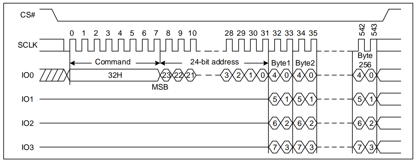
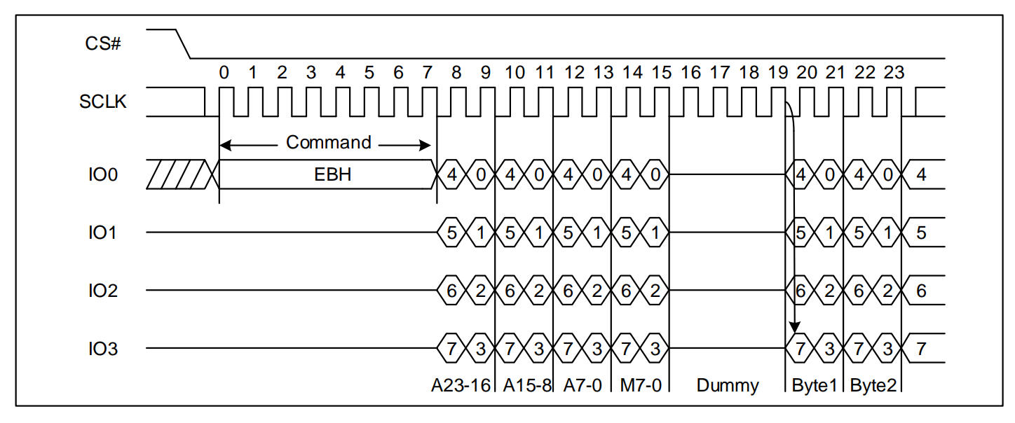
- 读操作
命令+读数据阶段命令+地址+读数据阶段命令+地址+dummy+读数据阶段命令+地址+模式+dummy+读数据阶段
示例:4线快速读命令序列
-
传输模式分类
- 根据数据传输的
位宽,可分为:
SPI: 单线模式DPI: 双线模式QPI: 4线模式OPI: 8线模式
- 根据数据传输的
边沿,可分为:
SDR: 单边沿传输DTR/DDR: 双边沿传输
- 根据数据传输的
4. 封装面向xSPI接口的的API
根据上述总结,以及update_instr_table的参数,我们实现了一套所见即所得的创建命令和传输命令的API。
4.1 抽象生成指令表项的函数
第一步,定义命令序列的上下文数据结构:
/**
 * @brief Instruction Sequence context
 */
typedef struct {
    uint32_t phase_idx; /*!< Phase index  */
    xpi_instr_seq_t seq; /*!< Instruction sequence entry */
} xpi_instr_seq_ctx_t;如上述代码块所示,我们定义了形成指令表的上下文结构体,其中phase_idx表示当前指令表使用的phase索引,seq表示当前使用的指令表。这里不探讨结节。
第二步,封装添加各个阶段功能的函数:
- xpi_instr_seq_init:初始化命令序列上下文。
- xpi_instr_seq_add_cmd_phase: 增加命令阶段。
- xpi_instr_seq_add_addr_phase:增加地址阶段。
- xpi_instr_seq_add_dummy_phase:增加dummy阶段。
- xpi_instr_seq_add_write_phase:增加写数据阶段。
- xpi_instr_seq_add_read_phase:增加读数据阶段。
最后,通过上述函数准备好命令序列后,实现以下功能函数:
- xpi_send_cmd:发送命令
- xpi_write_data:写数据
- xpi_read_data:读数据
以上和函数的详细原型介绍如下所示,其具体实现可在hpm_sdk/samples/rom_api/xpi_nor_api代码中获取。
/**
 * @brief Initialize the Instruction Sequence Context
 * @param [in, out] ctx Command Sequence Context
 */
void xpi_instr_seq_init(xpi_instr_seq_ctx_t *ctx);

/**
 * @brief Add the Command Phase to Instruction Sequence
 * @param [in,out] ctx Command Sequence Context
 * @param [in] cmd Command supported by the device (for example: Serial NOR FLASH, SPI ADC, etc)
 * @param [in] pads Pads used to send the CMD to device (valid value: 1/2/4/8)
 * @param [in] is_ddr Determine whether the command should be sent out in DDR mode
 */
void xpi_instr_seq_add_cmd_phase(xpi_instr_seq_ctx_t *ctx, uint8_t cmd, uint8_t pads, bool is_ddr);

/**
 * @brief Add the Address Phase to Instruction Sequence
 * @param [in,out] ctx Command Sequence Context
 * @param [in] addr_bits Address bits (for example, 24-bit / 32-bit)
 * @param [in] pads Pads used to send the address to device (valid value: 1/2/4/8)
 * @param [in] is_ddr Determine whether the address should be sent out in DDR mode
 */
void xpi_instr_seq_add_addr_phase(xpi_instr_seq_ctx_t *ctx, uint8_t addr_bits, uint8_t pads, bool is_ddr);

/**
 * @brief Add the Dummy Phase to Instruction Sequence
 * @param [in,out] ctx Command Sequence Context
 * @param [in] dummy_cycles Dummy cycles (for example, 4/6/8)
 * @param [in] pads Pads used to send the dummy to device (valid value: 1/2/4/8)
 * @param [in] is_ddr Determine whether the dummy should be sent out in DDR mode
 */
void xpi_instr_seq_add_dummy_phase(xpi_instr_seq_ctx_t *ctx, uint8_t dummy_cycles, uint8_t pads, bool is_ddr);

/**
 * @brief Add the Write Phase to Instruction Sequence
 * @param [in,out] ctx Command Sequence Context
 * @param [in] pads Pads used to send the data to device (valid value: 1/2/4/8)
 * @param [in] is_ddr Determine whether the data should be sent out in DDR mode
 */
void xpi_instr_seq_add_write_phase(xpi_instr_seq_ctx_t *ctx, uint8_t pads, bool is_ddr);

/**
 * @brief Add the Read Phase to Instruction Sequence
 * @param [in,out] ctx Command Sequence Context
 * @param [in] pads Pads used to read the data from device (valid value: 1/2/4/8)
 * @param [in] is_ddr Determine whether the data should be read out in DDR mode
 */
void xpi_instr_seq_add_read_phase(xpi_instr_seq_ctx_t *ctx, uint8_t pads, bool is_ddr);

/**
 * @brief Send command to Device
 * @param [in] base XPI base address
 * @param [in] chn XPI channel
 * @param [in] cmd_ctx XPI NOR command context
 * @param [in] addr Flash address
 *
 * @return status after issuing command to device
 */
ATTR_RAMFUNC hpm_stat_t xpi_send_cmd(XPI_Type *base,
                                     xpi_xfer_channel_t chn,
                                     const xpi_instr_seq_ctx_t *cmd_ctx,
                                     uint32_t addr);

/**
 * @brief Write data to Device
 * @param [in] base XPI base address
 * @param [in] chn XPI channel
 * @param [in] cmd_ctx XPI NOR command context
 * @param [in] offset The device offset that the data will be written to
 * @param [in] buf buffer that hold the data to be written
 * @param [in] bytes_to_write size for the data to be written
 */
ATTR_RAMFUNC hpm_stat_t xpi_write_data(XPI_Type *base,
                                       xpi_xfer_channel_t chn,
                                       const xpi_instr_seq_ctx_t *cmd_ctx,
                                       uint32_t offset,
                                       const void *buf,
                                       uint16_t bytes_to_write);

/**
 * @brief Read out data from Device
 * @param [in] base XPI base address
 * @param [in] chn XPI channel
 * @param [in] cmd_ctx XPI NOR command context
 * @param [in] offset The device offset that the data will be written to
 * @param [in] buf buffer that hold the data read out from device
 * @param [in] bytes_to_write size for the data to be read out
 */
ATTR_RAMFUNC hpm_stat_t xpi_read_data(XPI_Type *base,
                                      xpi_xfer_channel_t chn,
                                      const xpi_instr_seq_ctx_t *cmd_ctx,
                                      uint32_t offset,
                                      void *buf,
                                      uint16_t bytes_to_read);
5. 实战:实现读厂商ID的操作
以GD25Q128E为例,实现读厂商ID命令操作序列。
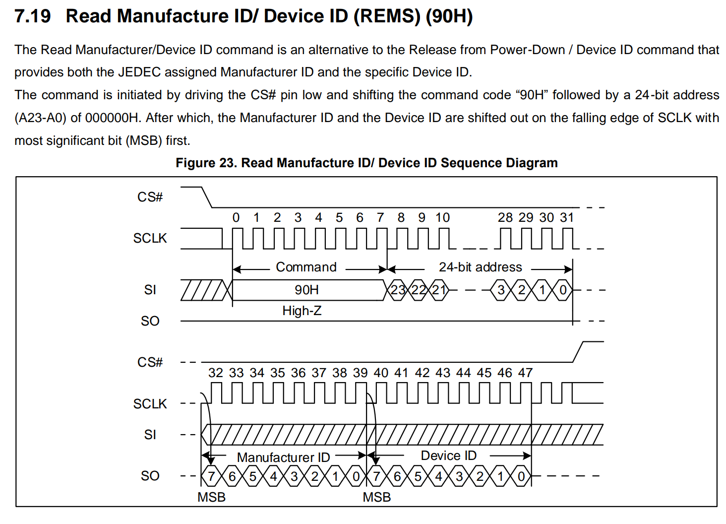
根据上图,该命令共有三个阶段:
- 命令阶段:0x90
- 地址阶段:24位地址,地址为0。
- 读阶段:1-2个字节
封装读MID函数:
ATTR_RAMFUNC hpm_stat_t read_mid_did(XPI_Type *base, xpi_xfer_channel_t chn, uint8_t *mid_did, uint32_t size_in_bytes)
{
    if ((base == NULL) || (mid_did == NULL) || (size_in_bytes == 0)) {
        return status_invalid_argument;
    }
    /* 创建命令序列 */
    xpi_instr_seq_ctx_t ctx;
    xpi_instr_seq_init(&ctx);
    xpi_instr_seq_add_cmd_phase(&ctx, 0x90, 1, false);
    xpi_instr_seq_add_addr_phase(&ctx, 24, 1, false);
    xpi_instr_seq_add_read_phase(&ctx, 1, false);

    /* 读寄存器 */
    return xpi_read_data(base, chn, &ctx, 0, mid_did, size_in_bytes);
}
代码调用:
    uint8_t mid_did[2]  = { 0 };
status = read_mid_did(base, chn, mid_did, sizeof(mid_did));若上述API执行成功,则mid_did[0]存储了厂商ID0xC8,mid_did[1]存储了设备ID0x17。
注:所有的操作基于FLASH已完成初始化的前提。
6. 总结
本文通过对XPI底层API常用操作的封装,实现一套基于XPI接口面向xSPI接口通信的所见即所得的API。后续用户可通过组合上述API,实现FLASH上的多种高阶功能,我们也将针对FLASH的典型应用场景,分别介绍这些API的使用。
关于本文中API的实现以及使用示例,请参考hpm_sdk/samples/rom_api/xpi_nor_api中的示例。
7. 附录
相关参考资料:
| 规范编号 | 规范标题 |
|---|---|
| JESD216 | Serial Flash Discoverable Parameters (SFDP) |
| JESD251 | EXPANDED SERIAL PERIPHERAL INTERFACE (xSPI) FOR NONVOLATILE MEMORY DEVICES |